CKMB 4000 DVB-T2 modulator
- BrandCEKE
- TypeCKMB 4000

Product introduction
Modulator is an important part of the terrestrial digital television broadcasting system, and also the core component of the transmitter.
The DVB-T2 Modulator developed by our company is composed of baseband processing, digital frequency synthesis, frequency converter, digital analog conversion, RF output, IP code flow input / output, monitoring system, control panel and other functional modules. It can realize the conversion from baseband data stream to DVB-T2 standard terrestrial digital television broadcasting RF signal.
It supports multi frequency network (MFN) and single frequency network (SFN) mode. The system block diagram is shown in Figure 1.
This product adopts a new design of digital predistortion (DPD). Through high speed and high precision sampling and digital signal analysis of the RF feedback signal, the baseband signal is predistorted adaptively, and the linear and nonlinear distortion of the RF output level is compensated by reverse, which greatly improves the performance and efficiency of the transmitting system. Rate. This technique can not only compensate for the linear / nonlinear distortion of the power amplifier system, but also correct the linear distortion caused by the output level passive devices, so as to improve the performance and signal quality of the transmitting system.
This product uses direct digital frequency synthesizer and digital frequency converter to make the digital domain close to the RF side to the maximum, and provide excellent system performance with excellent digital signal processing algorithm.
This product provides RS232/RS485/ network monitoring interface, so that the management system can monitor the operating state of the Modulator, and can upgrade the system through the network to realize the unmanned system of the transmitting system.

Figure 1 DVB-T2 Modulator system block diagram
Product appearance
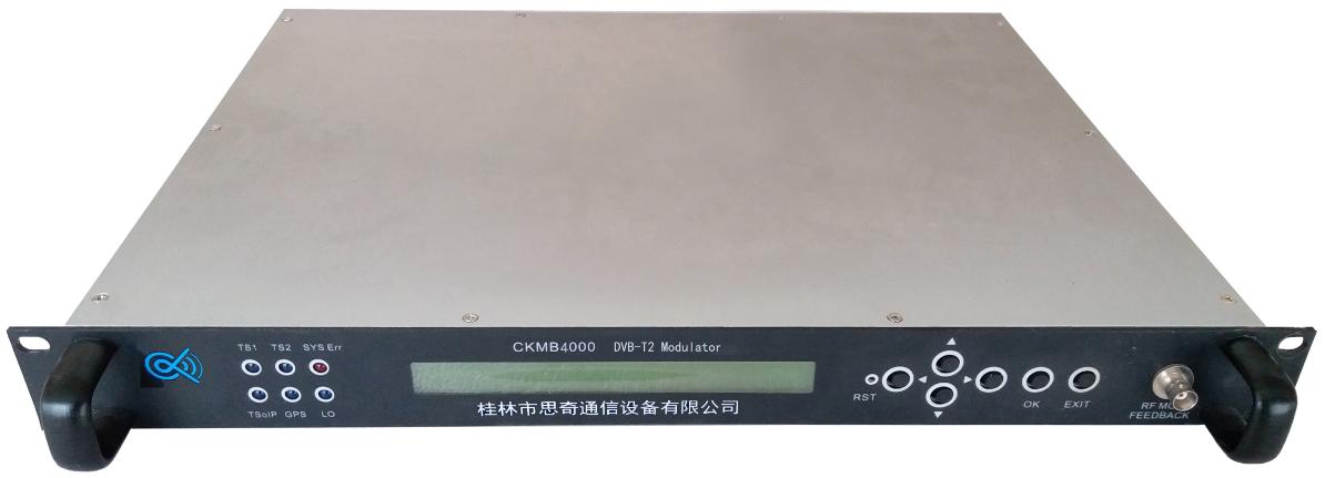
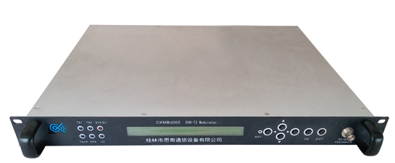
Product front view
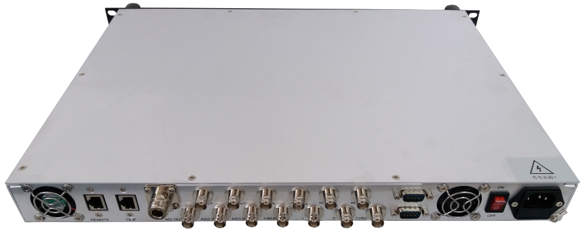
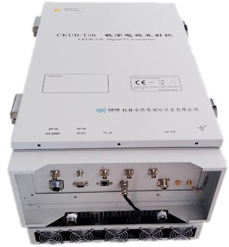
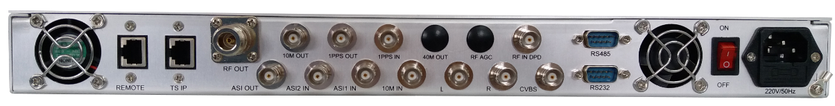
Product Back view
Product front panel diagram

Product front panel diagram
LCD: 40 x 2 character type LCD screen with backlight..
Function button: LEFT、RIGHT、UP、DOWN、OK、EXIT.
TS1: The light indicates the TS stream input from ASI1 IN is normal
TS2: The light indicates the TS stream input from ASI2 IN is normal
Lo: The light indicates the local oscillator works normal
TSoIP: The light indicates the system is using IP signal and it’s normal
GPS: The light indicates that the external GPS has been connected.
SYSErr: The light is on all the time indicates that there is a system failure
The lights flashing indicate that there is a system warning. Please check the LCD screen information.(See Chapter 6 ).
RF MON: RF signal output monitoring(The output level is lower than the [RFOUT] output level 10dB)
Product back panel diagram
Product front panel diagram
|
ASI OUT |
Stream output 1,BNC-K female,output impedance 75Ω |
|
ASI2 IN |
Stream output 2,BNC-K female,output impedance 75Ω |
|
ASI1 IN |
Stream output 3,BNC-K female,output impedance 75Ω |
|
10M IN |
10MHz clock input,BNC-K female,input impedance 50Ω |
|
10M OUT |
10MHz clock output, BNC-K female,output impedance 50Ω |
|
1PPS OUT |
1PPS output,BNC-K female,output impedance 50Ω |
|
1PPS IN |
1PPS input,BNC-K female,input impedance 50Ω |
|
RF IN DPD |
Pre corrected RF input signal |
|
RF OUT |
RF signal output,N-Kf emale,output impedance 50Ω |
|
40M OUT |
40MHz local oscillator output, reserved functional interface |
|
RF AGC |
reserved functional interface |
|
L |
Left channel input,reserved functional interface |
|
R |
Right channel input,reserved functional interface |
|
CVBS |
Video signal input,reserved functional interface |
|
RS232/RS485 |
Remote control, monitoring interface, RS232, DB9 male |
|
REMOTE |
Ethernet port (REMOTE) supports TCP protocol and UDP protocol |
|
TS IP |
RJ45 ,IPs ignal input |
|
Power switch |
Lamp ship type switch |
|
Power interface |
Three core power sockets with insurance |
|
Grounding terminal |
Grounding terminal |
Main characteristics
1) Fully comply with the technical specifications defined in the DVB-T2 (EN302 755) standard.
2) Adopt the newly designed digital predistortion (DPD) technology to realize adaptive linear and nonlinear pre correction function.
3) Use direct digital frequency synthesizer and digital frequency converter to make the digital domain close to the RF side to the maximum, and provide excellent system performance with the excellent digital signal processing algorithm.
4) Built-in rate adaptive module, which has high precision PCR correction function, and supports real-time display of input bit rate.
5) Real time temperature monitoring and display, providing overheating alarm function.
6) The RS232/RS485/ network monitoring interface is provided to facilitate the monitoring of the working state of the modulator, and the system can be upgraded through the network to realize the unmanned system of the transmitting system.
7) Provide two user interfaces —— LCD and WEB.
Technical Specifications
Physical parameters
Table 1 DVB-T2 modulator physical parameters
|
No |
Item |
Parameters |
|
1 |
environment temperature |
Normal operating:5 oC ~ 45 oC Allowable operating:0 oC ~ 50 oC |
|
relative humidity |
Normal operating:≤ 90% Allowable operating:≤ 95%(Non Condensing) |
|
|
atmospheric pressure |
86 kPa ~ 106 kPa |
|
|
2 |
Voltage amplitude |
176V~ 264V AC |
|
Power frequency |
50±1Hz |
|
|
3 |
Dimension |
Standard 1U chassis |
|
4 |
Weight |
Net weight 3.5 kg, gross weight 5 kg |
Technical parameters
Table 2 DVB-T2 Modulator Technical parameters
|
No |
Item |
Parameters |
||
|
1 |
Bit stream input |
1 way IP, 2 way TS input hot standby, automatic / manual seamless change-over |
||
|
Support 188/204TS flow, support Packet/Burst mode, automatic identification |
||||
|
interface type:BNC-K female,input impendance 75 Ω |
||||
|
2 |
Modulation and channel coding |
nominal effective bandwidth |
7.56 MHz @ -3dB |
|
|
modulation subcarrier number |
C = 1,C = 3780 |
|||
|
internal error correction code ratio |
0.4,0.6,0.8 |
|||
|
external error correcting code |
BCH |
|||
|
interleaving depth |
240,720 |
|||
|
protection interval |
PN420,PN595,PN945, 420 rotated,945 rotated |
|||
|
constellation mapping |
4QAM-NR,4QAM,16QAM,32QAM,64QAM |
|||
|
network mode |
Support single frequency network (SFN) and multi frequency network (MFN) |
|||
|
single frequency network time delay range |
0 ~ 999.9999 ms |
|||
|
single frequency network delay step |
100 ns |
|||
|
3 |
RF output |
central frequenct |
Comply with GB/T 14433-1993 0.1 Hz step adjustable |
|
|
RF output signal level |
-39.9 dBm ~ +9.9 dBm,0.1 dB step adjustable |
|||
|
RFMON signal level |
RF/ local oscillator monitoring output ,lower than RF output level of about 10dB |
|||
|
level stability |
< ±0.2 dB (24 hours) |
|||
|
frequency stability |
internal reference source:<1´10-7 external reference source:<1´10-10 |
|||
|
frequency accuracy |
MFN mode:±100 Hz |
|||
|
SFN mode:±1 Hz |
||||
|
SFN Frequency adjustment step |
0.1 Hz |
|||
|
MER |
> 46 dB |
|||
|
inband spectrum ripple |
<±0.5dB @central frequency ±3.591 MHz |
|||
|
signal band shoulder ratio |
< -50 dBc @central frequency ±4.2 MHz |
|||
|
outband spurious |
< -50 dB(inside adjacent channe,relative to total power) |
|||
|
< -55 dB(outside adjacent channe,relative to total power) |
||||
|
phase noise |
< -60 dBc/Hz(at 10 Hz) |
|||
|
< -75 dBc/Hz(at 100 Hz) |
||||
|
< -85 dBc/Hz(at 1 KHz) |
||||
|
< -95 dBc/Hz(at 10 KHz) |
||||
|
< -110 dBc/Hz(at 100 KHz) |
||||
|
< -120 dBc/Hz(at 1 MHz) |
||||
|
output interface type |
N-K female,impendance 50 Ω |
|||
|
4 |
Reference clock: internal |
stablity |
< ±0.01 ppm(Typical value) |
|
|
aging rate |
< ±0.3 ppm/year |
|||
|
Reference clock: external 10Mhz |
input level |
AC couple,VP-P ≥ 300 mV |
||
|
input interface |
BNC-K female,Impedance 50 Ω |
|||
|
Reference clock::external 1 PPS |
input level |
TTL |
||
|
trigger |
Rising edge triggering |
|||
|
input interface |
BNC-K female,Impedance 50 Ω |
|||
|
5 |
Linear and nonlinear pre-correction |
feedback input interface |
BNC-K female,Impedance 50 Ω |
|
|
feedback input level range:-30 dBm ~ -5 dBm, recommended value:-15 dBm |
||||
|
Self-adaptive: no auxiliary equipment is required |
||||
|
High efficiency: the whole system correction time is less than 10 minutes |
||||
|
High performance |
Correction of amplitude, phase and group delay error at the same time |
|||
|
MER improved 10 dB after whole system pre correction (typical value) |
||||
|
Nonlinear correction improved 15 dB (typical value) |
||||
|
In-band flatness improved ±0.5dB(before、after the filter)after correction (typical value) |
||||
|
6 |
control mode |
local control |
Front panel has six button control, 40 x 2 LCD screen, status indicator light |
|
|
remote control |
WEB interface, RS232/RS485/ network monitoring, support remote upgrade |
|||
|
7 |
Monitoring and alarm |
RF local oscillation unlock |
||
|
over-heat |
||||
|
Single frequency network can not analyse SIP, SIP CRC error, single frequency network state failure. |
||||
|
Input interrupt, input non TS stream format, input code rate more than the maximum net rate, PCR interval is too long. |
||||
|
reference clock source failure |
||||